


Many PreSonus products are equipped with standardized digital audio inputs and outputs, enabling them to transfer digital audio to and from an assortment of devices without conversion to and from the analog domain. Some PreSonus products also have dedicated, standardized connections for digital-audio synchronization signals. To help you understand these technologies, we’ve prepared a brief tutorial on digital connections and synchronization.
Digital Connection Types
ADAT Optical
 The Alesis ADAT modular digital multitrack tape recorder allowed users to record eight tracks of digital audio simultaneously. The ADAT Optical interface protocol, commonly referred to as “ADAT Lightpipe,” was developed to stream eight channels of 16-, 20-, or 24-bit digital audio at 44.1 kHz or 48 kHz, allowing multichannel digital transfers between ADAT digital recorders and other digital audio devices over a single fiber-optic cable. The ADAT Lightpipe format has been adopted by many audio manufacturers because it's a compact way to transfer multichannel digital audio data between devices.
 ADAT Lightpipe uses the same type of optical cables and Toslink connectors as the S/PDIF two-channel optical digital audio protocol (discussed shortly). These cables can be purchased at your local recording-equipment store. Toslink is an optical-fiber connection system developed by Toshiba that uses a JIS F05 connector. The generic name for this standard is “EIAJ optical.”
Today, many audio interface manufacturers use ADAT optical and its cousin S/MUX (more on that in a minute) to provide an easy and affordable way to add inputs and outputs to your recording rig when needed. PreSonus uses ADAT Lightpipe I/O on both the Studio 192-series and the Quantum-series interfaces for exactly this purpose. For example, the Studio 192 Mobile is only equipped with four analog inputs, making it compact enough to fit in your laptop bag. But because of its ADAT I/O, it can be expanded to record up to 22 inputs simultaneously, simply by adding an ADAT-equipped converter, like the DigiMax-series preamps.
 The DigiMax D8 is a companion 8-channel preamp with ADAT output to expand the inputs of any audio interface with an ADAT input. The DigiMax DP88 takes this a step further, by offering both ADAT input and ADAT output, allowing you to expand both the inputs and the outputs of your ADAT-equipped audio interface.
It should be noted that ADAT is a universal protocol. So, even if your audio interface was built by another manufacturer, if it has ADAT inputs and/or outputs, you can connect it to other ADAT-equipped devices. Just be sure to read the section on digital synchronization!
S/MUX
“Sample Multiplexing” or S/MUX is used to transmit high-bandwidth digital audio using lower-bandwidth technology, such as ADAT Lightpipe. S/MUX works by joining two or more digital audio channels to represent a single higher-bandwidth channel. By using S/MUX technology, you can stream 8 channels of digital audio at 88.2 kHz or 96 kHz over the same Lightpipe connection originally designed to stream 16 channels of 44.1 kHz or 48 kHz audio.
The Studio 192-series and Quantum-series interfaces support S/MUX, allowing you to recording and playback 16 channels at 88.2 kHz or 96 kHz.
The DigiMax DP88 also supports S/MUX, allowing you to add eight channel of analog I/O to any S/MUX-equipped device.
AES/EBU
 Developed by the Audio Engineering Society and the European Broadcasting Union, AES/EBU (officially known as AES3) is a 2-channel format that can carry audio signals at up to 192 kHz. AES/EBU employs a 3-pin XLR connector, which is the same connector used for most professional microphones. A single cable carries both channels of audio data. The StudioLive Series III console mixers are each equipped with an AES/EBU output.
S/PDIF
 S/PDIF (Sony/Philips Digital Interface) was co-developed by Sony and Philips to transfer stereo digital audio. It is essentially a consumer version of AES/EBU, and as with AES/EBU, a single cable carries both channels of the stereo audio signal. Digital Audio Tape (DAT) machines were among the first devices to be equipped with this protocol but is has since become popular in consumer audio products such as DVD players, as well as in semi-pro and professional audio products.
The most common connector used for S/PDIF is an RCA coaxial connector. While S/PDIF RCA coaxial uses the same connector as the analog RCA connection on consumer audio products, the cables are not the same, and these connections should not be confused. PreSonus products that offer S/PDIF RCA coaxial inputs and outputs include the Studio 68, Studio 192-series, and Quantum-series interfaces. The StudioLive RML-series digital mixers are equipped with a S/PDIF RCA output and the Central Station PLUS and Monitor Station V2 have a S/PDIF RCA input.
 S/PDIF also can be sent over Toslink optical connections, and these have become fairly common in semi-pro and professional audio gear. This is the same connector used for ADAT Lightpipe but the digital protocol is different. The Central Station PLUS offers a S/PDIF Toslink optical input, in addition to its S/PDIF RCA input; it is the only current PreSonus product that offers S/PDIF on Toslink.
Digital Clocking, Word Clock, and BNC
Digital clocking signals are used to synchronize digital audio signals flowing between devices to avoid data errors. Why is that necessary? Read on!
Analog audio is transferred through a cable as a continuous electrical waveform–it’s not divided into discrete steps—and electricity travels through a straight wire at almost the speed of light. So, when you route audio between analog devices, the signals arrive instantaneously, for practical purposes. Therefore, you don’t have to synchronize analog audio when routing between devices.
Transferring digital audio is a very different matter. Computers and other digital devices operate one step at a time, which happens very quickly but it’s not instantaneous, and digital signals are not inherently in perfect time. While uncompressed digital audio plays at a fixed rate (i.e. the sampling frequency), digital clocks are not perfect; their frequency can drift, and they almost always have at least some irregular errors, known as jitter. Therefore, two devices, each following its own clock, are highly unlikely to stay in agreement about precisely when a sample starts and ends. The result is usually an artifact: a pop or glitch in the audio.
To avoid this problem, all digital devices in communication with one another need to follow a single primary clock. That means the primary clock has to send a signal that essentially says, “everyone start at this moment and follow me!” Even if the primary clock’s timing is imperfect, all the secondary devices will follow the timing errors exactly and will stay in sync with each other. Therefore, you won’t get timing-related artifacts. In general, the better the primary clock, the better the resulting audio will sound, so whenever possible, use the best clock you have or experiment with your rig to find the best result.
There are three basic clocking systems in common use in digital-audio systems:
Self-clocking. In a self-clocking system, the clock signal is embedded in the audio stream. Samples are streaming in real time, with the clock marking the start time of each sample. The receiving device extracts the embedded clock signal from the digital audio. Self-clocking is implemented in every digital audio protocol (ADAT, S/PDIF, AES/EBU, etc.), and all PreSonus devices that offer these protocols employ self-clocking systems for those connections.
Distributed. Commonly used in professional environments with multiple digital devices, distributed clocking systems provide more stable clock because the clocking stream that does not contain audio. This makes the clocking stream cleaner than a self-clocking system. In a distributed system, sync signals and audio signals are separate. The clocking signal in a distributed clocking system is called word clock. (A word, in this case, is a fixed-size group of digital bits.) A word-clock generator creates digital pulses that control the frequency of the internal oscillator of each device to avoid frequency drift. Word clock does not carry location information, the way time code does, nor does it carry audio information; it only determines the rate at which samples should occur.
Word clock is used for a few types of distributed-clocking systems but the most common in professional audio uses a BNC connector. In this system, word clock is sent over dedicated, shielded, coaxial cables with standard twist-lock, BNC-type connections on each end. The cables are rugged and can carry clock signals much farther than standard optical cable. BNC connections are made in several impedances but PreSonus devices require an impedance of 75Ω to achieve consistent sync. Every PreSonus device equipped with ADAT, is also equipped with BNC word-clock for dedicated, stable clocking.
Reclocking. Computer transport protocols (FireWire, USB, Thunderbolt™) don’t use an embedded clock for timing; instead, they use a process called reclocking, in which the audio stream is divided into packets of data that are transmitted sequentially. The receiving device buffers the signal, reassembles the sample stream, and then sends the audio signal from the buffer at the appropriate time, as determined by the device's sample rate. This ensures accurate timing when going from an audio interface to a computer and back.
Synchronizing Multiple Digital Audio Devices
Whether you are using BNC or another digital output to generate word clock, it is necessary to designate one device as the “primary” word-clock device to which all other digital devices are synced. Many digital devices perform equally well as a primary or a secondary, although some devices must be one or the other. Synchronizing a device to a lesser-quality clock source is likely to degrade its performance, and not all word-clock generators are created equal. You generally need to determine which device has the best clock and to designate that device as the word-clock primary. This is done with careful listening and A/B testing.
Once you’ve determined which device is to be your primary clock, you will need to sync the remaining digital devices through series or parallel distribution or some combination thereof. Of course, if your digital-device chain only consists of one primary and one secondary, syncing the two is as simple as connecting a BNC word-clock cable from the output of your primary device to the input of the device you are slaving.
When working with multiple secondary devices, the job gets a bit more complicated.
Series distribution requires that your digital devices have both a BNC word-clock input and a BNC word-clock output.

Parallel distribution uses a BNC T-connector attached to the BNC word-clock input of each secondary device. This allows the word-clock signal to be sent to that device and then sent on to another device. A BNC word-clock output on the secondary devices is not used for parallel word-clock distribution. If the last device in the chain does not have a word-clock terminate switch, you will need to attach a BNC terminator plug to the other side of the T-connector. This helps to stabilize the word-clock sync and keep the word-clock signal clean. Both word-clock terminator plugs and BNC T-connectors can be purchased at most recording-supply retailers.

A third option for syncing your digital devices is to purchase a high-quality, dedicated word-clock generator. Many engineers believe that using dedicated word-clock generators enhances the performance of digital audio devices more effectively than series or parallel word-clock distribution. A dedicated word-clock generator and distribution amplifier exists for one purpose and one purpose only: to be a primary clock.
Word-clock generators usually have one BNC word-clock input and multiple BNC word-clock outputs, and sometimes they have AES, S/PDIF, or ADAT outputs to make them compatible with as many types of digital devices as possible. Without a dedicated word-clock generator, it is necessary to split the primary device’s word-clock signal by daisy-chaining the secondary devices as described earlier. Because of this, many engineers feel that the resulting digital audio signals will be of a higher quality when a dedicated word-clock generator is used; in this way, all digital devices are receiving the same digital pulse from the same source at exactly the same time.
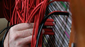
Whichever approach you use, it is always advisable to use quality BNC cables that are no longer than necessary for the job. As with audio cabling, it is good to keep word-clock cables separate from AC cable lines or other possible sources of interference.
FURTHER READING
-
It's Only Ones and Zeros
from Recording magazine
Keeping Audio in Sync: Wordclock Solutions
from Studiodaily.com
Ten Minute Master: Staying in Sync
from Music Tech magazine
Wire We Doing This?
from Recording magazine